A solar array is only as dependable as the connections holding it together. A rail may be strong enough on paper yet incompatible with a clamp; a cable clip may fit the frame but leave a connector hanging; a grounding lug may be correctly specified but installed on an unapproved surface. Choosing solar PV mounting hardware therefore means checking the complete assembly, not collecting parts with familiar names. This guide explains what each accessory does, how materials and interfaces affect selection, and which installation checks help prevent avoidable rework.
1. Match Solar Mounting Rails, Brackets and Clamps as a System
Mounting rails and brackets carry the load
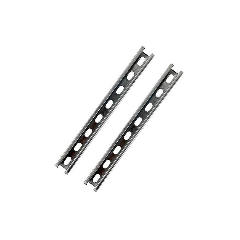
Solar mounting rails provide the continuous support on which modules are fixed. Brackets connect that support to the roof or ground structure. A useful procurement drawing shows the rail cross-section, slot geometry, length, coating, bracket hole pattern and connection details. It should also identify the design loads and the substrate receiving the attachment. A rail profile cannot be approved from width and height alone: wall thickness, span, fastening arrangement and the engineer's load calculation matter too.
For example, a project may compare a hot-dip galvanized PV U-channel rail with a C steel PV mounting rail. The choice depends on the approved design and mating hardware, not a generic preference for one profile. Likewise, a PV base bracket must fit the specified structural member and attachment method. Request drawings before treating any bracket as interchangeable.
Mid clamps and end clamps need exact interfaces
A mid clamp secures neighboring module edges; an end clamp secures the outer edge of a row. Both must match the module frame, approved clamp zone, rail slot, bolt engagement and prescribed tightening method. Module frame height is only one dimension. Contact area, frame shape and the manufacturer's mounting instructions can change whether a particular PV mid/end clamp is suitable.
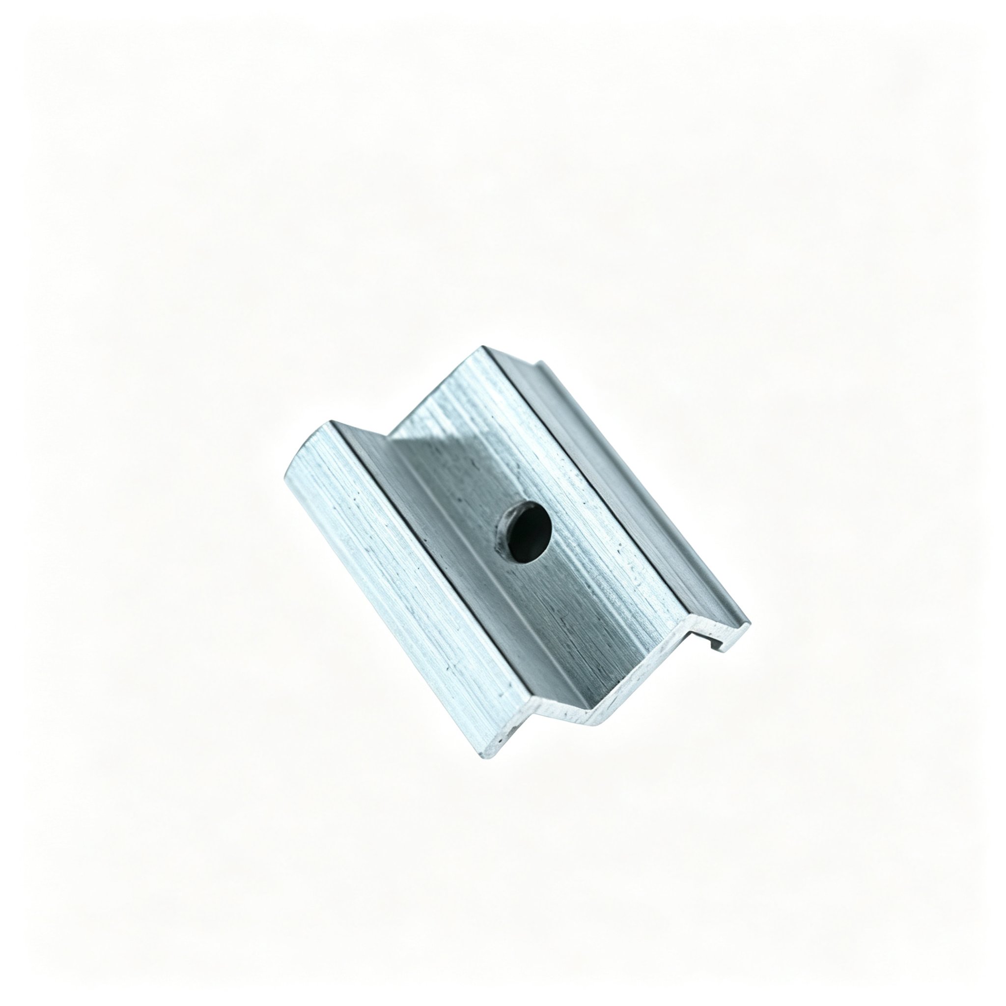
Avoid assuming that a clamp also creates an electrical bonding path. That function depends on the tested assembly, approved components and installation conditions. UL Solutions explains that mounting devices, clamping devices and ground lugs can have different evaluated functions. Ask for the exact documentation relevant to the module and racking combination in your project.
Bolts and nuts complete the mechanical joint
Even a well-selected rail and clamp can fail as a system if the fastener stack is wrong. Specify bolt diameter and length, thread engagement, washer arrangement, nut type, coating and required torque as a set. A hot-dip galvanized hex bolt and a matching hex nut are procurement starting points, not proof that every rail or bracket joint is approved. Confirm the engineer's connection detail and the fastener supplier's instructions before substitution.
2. Choose Materials for Exposure and Compatible Connections
Galvanized steel, stainless steel and aluminum have different roles
Material selection is about the actual environment and the assembly. Hot-dip galvanized steel is commonly considered for structural rails and brackets; SS304 is often used for cable-management accessories and selected fasteners; aluminum is common in module clamps and some rail designs. Coating type and thickness, cut edges, water retention and local exposure all deserve review. Do not infer a service life from a material name alone.
Mixed metals also require attention. An aluminum clamp against coated steel, or a stainless fastener through another metal, may introduce galvanic-corrosion concerns when moisture is present. The appropriate isolation or compatible hardware should come from the approved system design. Also check whether field drilling, grinding or cutting changes the coating protection and requires a documented repair method.
Ask for evidence tied to the part you will install
For solar panel mounting accessories wholesale orders, generic catalogue descriptions are insufficient. Request material grades, coating details, dimensional drawings, inspection criteria and packaging information for the exact part number. If dimensions are customized, validate a sample against the mating rail, module frame or bracket before bulk production. This reduces the risk of receiving a component that looks similar but cannot be assembled consistently on site.
3. Keep Solar Cable Clips and Grounding Hardware in Their Proper Roles
Solar cable management clips protect the route
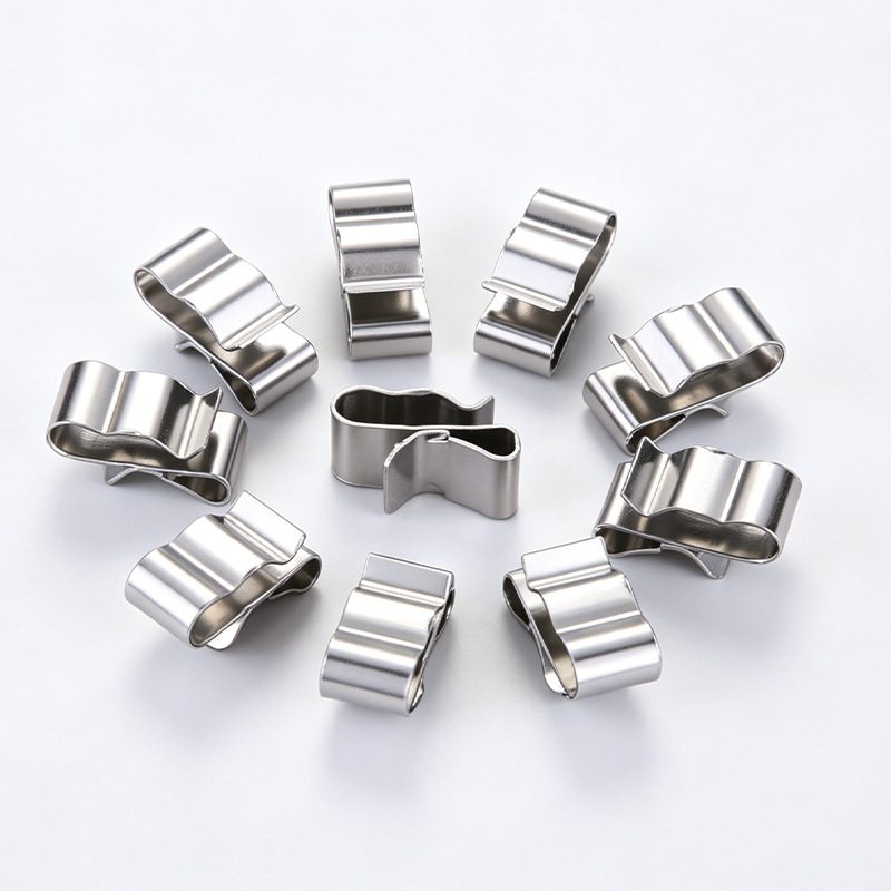
DC cables should be supported and routed away from sharp edges, abrasive surfaces, standing water and moving parts. A clip must match the actual cable outside diameter or approved cable count, as well as the frame or rail edge where it attaches. Leave the bend radius and connector clearance required by the cable and connector manufacturers. The goal is an orderly route that can be inspected and maintained, not merely a neat photograph.
The U.S. Department of Energy's PV cable-management guidance warns that ordinary plastic ties can fail under outdoor exposure and discusses durable alternatives. For a specific application, compare SS304 solar cable clips and UV-resistant plastic cable clips against the cable, mounting edge and environmental conditions. A UV-resistant label alone does not prove compatibility with every cable jacket or site.
Grounding lugs and bonding devices require system approval
Grounding and bonding are electrical functions, not visual features. A grounding lug or PV grounding terminal must be selected for the approved conductor, metal interface and installation method. Check surface preparation, fastener torque and whether the device is evaluated for the particular rail or frame combination. A mechanical clamp should not be credited as a bonding component unless the approved system documentation explicitly allows it.
This is especially important when an installer replaces a rail, coating, clamp or washer with a seemingly equivalent part. A substitution can alter the bonding path even when the mechanical connection still feels secure. Keep the electrical design, local code requirements and inspection records aligned with the exact hardware installed.
4. Turn the Product List Into an Installation-Ready BOM
Before ordering: describe interfaces, not just quantities
A useful bill of materials identifies each rail, bracket, clamp, cable clip, grounding device, bolt and nut with its mating component. Include three groups of information:
- Mechanical fit: drawings, module model and frame dimensions, rail profile, clamp zone and substrate.
- Electrical and cable routing: cable outside diameter, connector clearance and specified bonding method.
- Procurement: materials and coatings, project location, quantities, destination and approved alternatives.
For a PV mounting hardware supplier, these details make a comparison quotation more meaningful than a list of broad product names.
Plan for tolerances and site logistics too. Ask how rail lengths will be packed, whether mixed accessory orders are possible, and which dimensions require sample approval. Separate structural or electrical approval from commercial acceptance: a competitive price cannot compensate for a part that fails the approved interface.
During installation: verify the assembled system
Use the module and racking manufacturers' instructions for clamp positions, fastener torque and attachment details. Check that rail splices, brackets and fasteners match the drawings; that cables remain supported without abrasion or excessive tension; and that bonding connections use the specified hardware. Record any approved substitutions rather than improvising them in the field. The U.S. Department of Energy also highlights fastener installation practices as part of PV resilience planning.
After installation, inspect accessible joints, cable routes and grounding points before handover. A clear as-built record helps the O&M team identify the actual parts if a clip, clamp or rail section later needs replacement.
Conclusion. Solar PV mounting hardware works best when rails, brackets, clamps, fasteners, cable supports and grounding components are specified as one compatible system. Start with the approved design, verify every interface, and keep documentation with the installed hardware.
Discuss your BOM. RONGYIDA PV SOLAR is a professional China-based manufacturer of PV mounting accessories, with factories in Wenzhou and Handan. We support project-specific dimensions and competitive pricing. Send us your drawings or BOM to request specifications, samples or an indicative quotation.
FAQ: Solar PV Mounting Hardware
Are PV mid clamps and end clamps interchangeable?
No. Their positions and contact geometry differ, and each must match the module frame, approved clamp zone, rail and fastener stack. Check the system instructions before ordering or substituting either clamp.
Are stainless steel cable clips always better than plastic clips?
Not automatically. Compare attachment fit, cable compatibility, outdoor exposure and documented performance. A suitable UV-resistant plastic clip may work in one application, while a stainless clip may be preferable in another.
Can a mounting clamp replace a grounding lug?
Only if the approved system documentation explicitly assigns it that bonding function for the exact components and installation method. Otherwise, use the specified bonding or grounding hardware.
What should I send when requesting a mounting hardware quotation?
Send the project BOM, rail and module drawings, required materials and coatings, cable dimensions, quantities, destination and any approval or sample requirements. The more precise the interfaces, the more useful the quotation.